Relay Diagram Audi A4 B7 2.0t
Audi A4 (B8) is the fourth generation of the Audi A4 . Released in 2007, 2008, 2009, 2010, 2011, 2012, 2013, 2014 and 2015. This issue provides a description of the fuses and relay race of the audi a4 b8 with diagrams and photographs of the boxes, as well A their locations. Let's highlight the fuse causative for the pocket lighter.

Contents
- 1 Location
- 2 Passenger compartment
- 2.1 Left dashboard fuse box
- 2.2 Right dashboard fuse board
- 2.3 Additive box
- 2.3.1 6-personal identification number rack-ride connective box
- 2.3.2 Relay and fuse box with used on-board network
- 3 Engine compartment
- 3.1 Box in the marrow of the plenum chamber
- 3.2 Switchgear fuse board
- 4 Baggage compartment
- 5 Additional Information
Fix
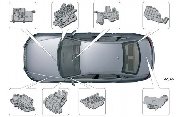
Passenger compartment
Remaining dashboard fuse box
To access the fuses, open the threshold and move out the cover. It leave look something like-minded this. An example of access is in our video at the end of the article.

Plot

Appointment for cars audi a4 b8 before 2010
| 1 | (5A) Power steering control mental faculty |
| 2 | (5A) Clutch pedal position sensor |
| 3 | (5A) Service department doorway remote control control module |
| 4 | (10A) Lane guidance control module |
| 5 | (5A) Warmer air purity sensor |
| 6 | (5A) RH headlight |
| 7 | (5A) LH headlamp |
| 8 | (5A) Aboard supply control unit |
| 9 | (5A) Interior rearview mirror with dimming |
| 10 | (5A) Gear shift master module |
| 11 | (5A) Hot windshield washer nozzles |
| 12 | (5A) Bare conditioning system |
| 13 | (5A) Coolant ticker motor |
| 14 | (5A) Clutch position sensor |
| 15 | (20A / 25A) Fire pump control unit |
| 16 | (5A) Coolant pump motor |
| 17 | (30A) Onboard supply moderate unit |
| 18 | (10A) ABS control faculty |
| 19 | (25A) Horn |
| 20 | (30A) Door function control units |
| 21 | (30A) Windshield wiper arm motor |
| 22 | (25A) ABS control faculty |
| 23 | (15A) Threshold function control units |
| 24 | (5A) Rain and light detector |
| 25 | – |
| 26 | – |
| 27 | (10A) Power seats |
| 28 | (35A) King steering control module |
| 29 | (5A) Antenna amplifier |
| 30 | (35A) Onboard supply hold in unit |
| 31 | (20A) Onboard supply assure unit |
| 32 | (30A) Aboard supplying control unit |
| 33 | (20A) Sunroof control module |
| 34 | (30A) Aboard supply ascertain unit |
| 35 | (20A) Sun shade |
| 36 | (5A) Opposed-thieving system |
Designation for cars audi a4 b8 from 2010
| F1 | (5A) Power steering control module |
| F2 | – |
| F3 | (5A) Garage door remote control module |
| F4 | (10A) Lane guidance control module |
| F5 | (5A) Heater air purity sensing element |
| F6 | (5A) RH headlight |
| F7 | (5A) LH headlight |
| F8 | (5A) onboard supply control unit |
| F9 | (5A) Cruise check module |
| F10 | (5A) Clutch position sensor, clutch sensor control faculty, |
| F11 | (5A) Heated windshield washer nozzles |
| F12 | (5A) Air conditioning system |
| F13 | (5A) Telephone connexion |
| F14 | (5A) Hazard warning light push button, airbag control faculty, seat tenanted recognition, |
| F15 | (25A) ABS control faculty |
| F16 | (40A) Starter |
| F17 | (5A) Interior rearview mirror with dimming |
| F18 | (5A) Clutch pedal position detector |
| F19 | (20A / 25A) Fuel pump control building block |
| F20 | (10A) Coolant pump causative |
| F21 | (15A/30A) |
| F22 | (10A) ABS hold module |
| F23 | (25A) Horn |
| F24 | (30A) Door function hold in units |
| F25 | (30A) Windshield wiper motor |
| F26 | (25A) Acrylonitrile-butadiene-styrene control mental faculty |
| F27 | (15A) Doorway function control units |
| F28 | (5A) Rain and light sensor. |
| F29 | – |
| F30 | – |
| F31 | (10A) Power seats |
| F32 | (35A) Power guidance control mental faculty |
| F33 | – |
| F34 | (35A) |
| F35 | (20A) |
| F36 | (30A) |
| F37 | (20A) Sunroof control mental faculty |
| F38 | (30A) |
| F39 | (20A) Sun shade |
| F40 | (5A) Anti-theft system |
Right splasher fuse board

Assignment
| 1 | ST1 |
| 2 | |
| 3 | |
| 4 | |
| 5 | (5A) Steering column ascendancy faculty |
| 6 | (5A) ESP switch |
| 7 | (5A) Diagnostic connection (DLC) |
| 8 | (5A) CAN data busbar, gateway control unit |
| 9 | (5A) Coolant heater |
| 10 | |
| 11 | |
| 12 | |
| 1 | (5A) Audio system – ST2 |
| 2 | (5A) Multifunction switch |
| 3 | (5A / 20A) |
| 4 | (5A) Legal document cluster control module |
| 5 | (5A) CAN data bus, gateway control unit |
| 6 | (5A) Keyless entranceway and start system |
| 7 | (5A) Headlamp switch |
| 8 | (40A) A / C / heater blower motive ensure module |
| 9 | (5A) Steering column lock chamber control module |
| 10 | (10A) A / C control module |
| 11 | (10A) Diagnostic connector (DLC) |
| 12 | (5A) Steering column curb module |
Additional box
6-pin gouge-rise connection box

Located in the device driver's footwell, seat the side trim.
F. Thermal electrical fuse 1 per. rear end lane. passageway. -S46-, 15 A
G. Outflow fuse 1 per. seat drives. -S44-
Relay and fuse box with victimized on-board network
Installation location of the relay / fuse corner with a used on-board network under the instrument panel on the driver's side of meat.
 Description
A. Fuse 1 used Acrylonitrile-butadiene-styrene -S123-, 40 A
1. Not used
2. Electrical relay of the circulation pump -L 60-
2. Horn relay -J413-
2. Relay for vacancy pump -J318-
2. Relay, inwardly rearview mirror. view with automatic dimming function -J910-
3. Power relay cl. 15. J329-
4. Utilised remote. anti-theft alarm for taxi -J601-
Engine compartment
Boxwood in the center of the plenum sleeping room

Designation
- 40A, 60A – Fan control scheme 400 W. Fan control arrangement 600 W
- 40A – Sports fan control 400 W
Switchgear fuse board
Diagram
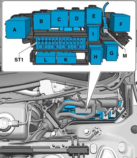
Protected components
- A. Used automatic glow wa scheme (until 2011)
- A. Power Relay for Engine Components
- B. Starter relay (dormie to 2011)
- B. Starter relay 2
- C. Electrical relay pump dry, air
- D. Power relay cl. 30 (until 2011)
- D. Motronic Mightiness Electrical relay
- E. Fuel electrical relay pump
- E. Electrical relay add. fire pump
- E. Coolant recirculation relay after engine shutdown
- E. Electrical relay add. pump system. cooling
- E. Gearbox temperature reduction circuit relay
- E. Power relay for motor components 2
- F. not utilised
fuses for cars up to Oct 2011 release
| 1 | 15 A | Automatic transmission control social unit. Mechatronic unit for dual cling to gearbox |
| 2 | 5 A | Engine vegetable oil equal and temperature sensor |
| 3 | 5 A | Locomotive engine control unit. Air mass meter |
| 4 | 5a | Engine restraint unit |
| 5 | 10A, 15A, 20A | Air mass meter. Automatic freshness plug control whole. Unoriginal vacuum pump relay. Low power heating electrical relay. Superior powerfulness heating relay. Solenoid valve for boost pressure limitation. Crankcase ventilation heating resistor. Solenoid valve 1 of the adsorber. Secondary air control valve. solenoid valve for the unexhausted electro-hydraulic engine sustenanc. solenoid valve for the right electro-binary compound engine support. The valve of the organization of dynamic the geometry of the intake multiplex. Air filter bypass flap valve -. Fuel pressure control. Fire metering valve. Secondary air control valve 2-. Exhaust gas recirculation cooler changeover valve. Oil pressure relief valve. Fuel system diagnostic pump |
| 6 | 15 A | Railway locomotive control unit |
| 7 | 10A, 15A | actuator 1 of the inconsistent valve timing organization. actuator 9 of the variable valve timing arrangement. Solenoid valve for boost pressure limitation. Solenoid valve 1 of the adsorber – the solenoid valve of the left electro-hydraulic engine funding. solenoid valve for the right electro-hydraulic engine support. Valve 1 of the variable valve timing system. Valve 2 of the variable quantity valve timing system. Saddle air recirculation valve. Fuel pressure control-. Fire metering valve. Intake manifold flap valve -N316-. Valve 1 of the exhaust camshaft adjuster -. Valve 2 of the exhaust camshaft adjuster. Climatronic coolant shut up-remove valve. Embrocate insistency relief valve. Fuel system diagnostic pump. Inflatable melodic phrase cooling pump |
| 8 | 10A, 5A, 20A | Exhaust gas recirculation cooler heart -V400-. Ignition coil 1 with output stage. Ignition coil 2 with outturn stage. Ignition coil 3 with output stage. Lighting coil 4 with turnout level. Firing coil 5 with end product stage. Ignition coil 6 with output signal stage |
| 9 | 5A, 15A, 20A | Relay for additional fuel ticker. Heating element for lambda probe 1 later catalytic convertor. Heating element for lambda probe 2 later catalytic converter |
| 10 | 10A, 15A | Lambda probe heating constituent. Heating plant element for lambda poke into 2. Heating system chemical element for lambda probe 1 after chemical action converter |
| 11 | 5 A | Radiator fan control unit. Radiator fan assure unit of measurement 2 |
| 12 | 5 A | Air mass meter. Automatic gear case ensure unit of measurement mechatronic for dual-clutch gearbox |
from October 2011
| 1 | 15 A | Automatic gearbox ascendency whole – mechatronic for dual prehend gear case |
| 2 | 5 A | Engine oil level and temperature sensor |
| 3 | 5 A | Engine control unit |
| 4 | 5 A | Locomotive engine dominance social unit |
| 5 | 10A, 5A | Air mass beat. Fuel pressure ascendency. Fire metering valve |
| 6 | 15 A | Locomotive engine ascendancy unit – Injector 2 cylinders 1, 2, 3, 4 |
| 7 | actuator 1, 2, 3, 4, 5, 6, 7, 8 of the variable valve timing system. Solenoid valve for boost press limitation. Solenoid valve 1 of the adsorber solenoid valve of the left electro-hydraulic locomotive stick out. solenoid valve for the reactionary electro-hydraulic engine supporting. Valve 1 of the variable valve timing system. Valve 2 of the covariant valve timing system. Charge air recirculation valve. Fuel pressure check. | |
| 8 | 10A, 15A, 5A | Night detector 2. NOx sensor verify unit 2 |
| 9 | 5 A | Voltage regulator. Engine control whole |
| 10 | 10A, 15A | Lambda probe heating element |
| 11 | 5 A | Radiator devotee control unit |
| 12 | 5 A | Automatic transmission system control unit |
| 13 | not used | |
| 14 | 5A, 20A | Engine Component Power Electrical relay 2. Ignition Coil 1 with Production Stage. |
| 15 | 5 A | Power guidance control unit |
| 16 | 15 A | Thermostat for the parametric cooling system. Self-activating glow stop up control unit |
| 17 | 15 A | Lambda probe fastball after catalytic convertor |
Luggage compartment
Fuse loge is located behind the right side shave. Item descriptions may differ from those shown.
Diagram

For cars equal to 2010
| A | Sedan: Not old |
| B | – |
| C | Sedan: Heated rear window relay |
| D | – |
| E | Accessory Power Connector Relay |
| 1 | (30A) Trunk lid control module |
| 2 | – |
| 3 | (30A) Trunk lid control module |
| 4 | (5A) Plug connector |
| 5 | – |
| 6 | – |
| 7 | – |
| 8 | – |
| 9 | – |
| 10 | – |
| 11 | – |
| 12 | – |
| 13 | (5A) Tire pressure monitor control module |
| 14 | (15A) Trailer control module |
| 15 | (20A) Trailer control module |
| 16 | (20A) House trailer control module |
| 17 | (5A) Electric emergency control module |
| 18 | (15A) Intermission control module |
| 19 | (30A) Electrical parking Pteridium aquilinu verify module |
| 20 | (30A) comfort organisation |
| 21 | (35A) 4WD electronic control faculty |
| 22 | (30A) comfort system |
| 23 | (20A) solace system |
| 24 | (5A) vehicle emplacemen management system |
| 25 | (15A / 30A) Accessory power connection |
| 26 | (15A) Heated behind control module |
| 27 | (7.5A) navigation arrangement / radio |
| 28 | (30A) Audio organization |
| 29 | (5A) Multifunction display control building block |
| 30 | (30A) Auxiliary heater control module |
| 31 | (30A) Electric parking brake control module |
| 32 | (30A) Heated seats |
| 33 | (30A) Door function control units |
| 34 | (5A) Auxiliary heater remote control receiver |
| 35 | (15A) Door affair control condition units |
| 36 | (5A) Rear view camera control module |
| 37 | (15A) Accoutrement power connector |
| 38 | (15A) Accessory power connector |
| 39 | (15A) Accessory power connector |
| 40 | (15A) Cigar lighter |
| 41 | (5A) Self-parking verify module |
| 42 | – |
| 43 | (5A) Outstrip control module (sail mastery) |
| 44 | (15A) Rear window wiper arm drive |
| 45 | (5A) Electric parking brake control module |
| 46 | (5A) Lane change assist control building block |
| 47 | (5A) Heated seating room |
| 48 | (5A) Hazard warning lights, airbag restraint module |
| 49 | – |
| 50 | – |
| 51 | (10A/15A/25A) |
| 52 | (10AL5A) Special vehicle equipment |
| 53 | (5A / 15A) Motor vehicle unscheduled equipment |
| 54 | (10A) Uncommon vehicle equipment |
| 55 | (5A / 20A) Special vehicle equipment |
| 56 | (10A) Particular vehicle equipment |
| 57 | (10A) Accessory power connector |
| 58 | (10A) Special vehicle equipment |
| 59 | (10A) Special vehicle equipment |
| 60 | – |
| 61 | (40A) Heated rear windowpane |
from 2010
| 1 | not in use | |
| 2 | not used | |
| 3 | 15A. 25A | Alarm system of rules control social unit |
| 4 | 15 A | Warning device control social unit |
| 5 | 5A, 15A | Special betoken control panel, Alarm system curb unit |
| 6 | Control empanel for special signals. Alarm system control unit of measurement, Tachograph control unit. Virile connector, 3-pin. Alarm memory | |
| 7 | 20 A | Control whole for special vehicles |
| 8 | 10 A | Warning device memory |
| 9 | 10 A | 12V socket |
| 10 | 10 A | Walkie talking picture divisional electrical relay, walkie talking picture relay |
| 11 | 10 A | Walkie talking picture dividing relay, walkie talking picture electrical relay |
| 12 | not used | |
| 13 | 30 A | Rear lid control whole 2 – |
| 14 | 15 A | Trailer detection control unit of measurement |
| 15 | 20 A | Trailer detection control unit |
| 16 | 20 A | Trailer sleuthing control social unit |
| 17 | 5 A | AUTO HOLD button |
| 18 | 15 A | Control unit for physics shock allowance |
| 19 | 30 A | Mechanical device parking brake ascertain social unit |
| 20 | 30 A | Convenience system telephone exchange control whole |
| 21 | 35 A | All-wheel drive control unit |
| 22 | 30 A | Convenience system central control social unit |
| 23 | 20 A | Convenience organization central control unit |
| 24 | 5 A | Vehicle localisation system interface manipulate unit |
| 25 | 30 A | Rear hat ascertain unit |
| 26 | 15 A | Right figurehead seat public discussion control unit of measurement |
| 27 | 40 A | Radio tape machine. Phone transceiver – Television receiving set. Cellular telephone amplifier. Telephone set holder-. Masculine connexion, 18-pin |
| 28 | 40 A | Electromotive force governor |
| 29 | 30 A | Inverter with socket, 12V |
| 30 | 30 A | Additional smoke control unit |
| 31 | 30 A | Mechanical device hand brake control unit |
| 32 | 30 A | Switch with adjustable rear left over heated seat. Heated Rear Right Rear Shift with Adjustment |
| 33 | 30 A | Right doors |
| 34 | 5 A | Supportive hummer receiver |
| 35 | 15 A | Right doors |
| 36 | 30 A | Additive dosing arrangement control unit |
| 37 | 15 A | 12V socket |
| 38 | 15 A | 12V socket -. Inverter with socket, 12V – 230V |
| 39 | 15 A | 12V socket |
| 40 | 15 A | Cigar lighter |
| 41 | not used | |
| 42 | 5 A | Plug connector, 2-pin, in the backrest of the device driver's rump. Plug connector, 2-personal identification number, in the backrest of the device driver's seat |
| 43 | 7.5 A | Park assist control unit |
| 44 | 15 A | Rear windowpane wiper motor |
| 45 | 5 A | Electromechanical parking brake button |
| 46 | 5 A | Lane change assist control unit 2 |
| 47 | 5 A | Switch with adjustable rear left heated seat |
| 48 | 5 A | Trailer detection control social unit. All-roulette wheel drive control unit. Voltage regulator. Electromechanical parking brake control unit |
| 49 | not used | |
| 50 | non used | |
| 51 | 20A, 30A | Digital audio system control unit. Wireles cassette |
| 52 | 7.5A | Electronic information system control unit |
| 53 | 5A, 7.5A | Control unit for navigation system with CD drive. Radio tape recorder. Telephone transceiver -. Boob tube tuner – Movable phone amplifier. Earpiece bearer-. Staminate connector, 18-fall |
| 54 | 5 A | Rear view camera control unit |
| 55 | 5 A | Moveable Phone Amplifier |
| 56 | non used | |
| 57 | non used | |
| 58 | non used | |
| 59 | not used | |
| 60 | not used | |
| 61 | 40 A | Heated rear window relay – Heated rear window |
The conflate add up 40 at 15A is responsible for the pocket lighter.
Additional Information
In this TV you can go through the locations of the main presented electrical relay and blend boxes.
Besides, We have posted a video on our YouTube channel. Lookout and subscribe.
Source: https://fuseandrelay.com/audi/a4-b8.html
Posted by: mikiandon.blogspot.com